Quantum Raspberry Tie
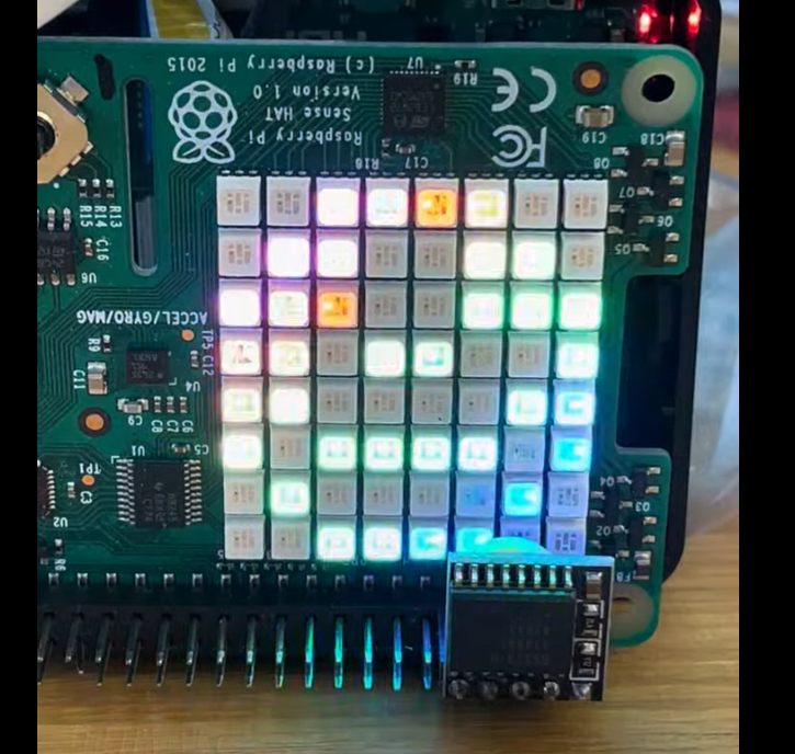
Run a quantum circuit — on a simulator or on real IBM Quantum hardware — and watch the measured qubits light up on the panel, laid out the way the qubits are actually arranged on the processor.
Needs: the LED panel · a display · an IBM Quantum account for the real variant
Start it with: rq_demo_run.sh quantum-raspberry-tie
Run it
Open the LED panel folder on the desktop and double-click Quantum Raspberry Tie.
It is also under Applications → RasQberry → Quantum Raspberry Tie, or in
sudo raspi-config → 0 RasQberry → Quantum Demos → LED panel.
From a terminal you can pick the backend:
rq_demo_run.sh quantum-raspberry-tie            # local Aer simulator (default)
rq_demo_run.sh quantum-raspberry-tie noise      # simulator with a noise model
rq_demo_run.sh quantum-raspberry-tie real       # real IBM Quantum hardware
The real variant needs a network connection and your IBM Quantum account, and
your job may sit in a queue before it runs.
Your IBM Quantum account: the real variant asks for your API key when none
is saved, and saves it. Or save it once: sudo raspi-config → 0 RasQberry →
IBM Quantum account → Save my API key.
What you'll see
Each qubit is a coloured pixel: blue for a qubit measured as |1⟩, red for |0⟩, and a paler shade for qubits that were not measured. The pixels are not in a line — they are placed to match the connectivity of a real IBM processor, so a 5-qubit run makes the "bowtie", and larger runs the heavy-hex pattern used by current devices.
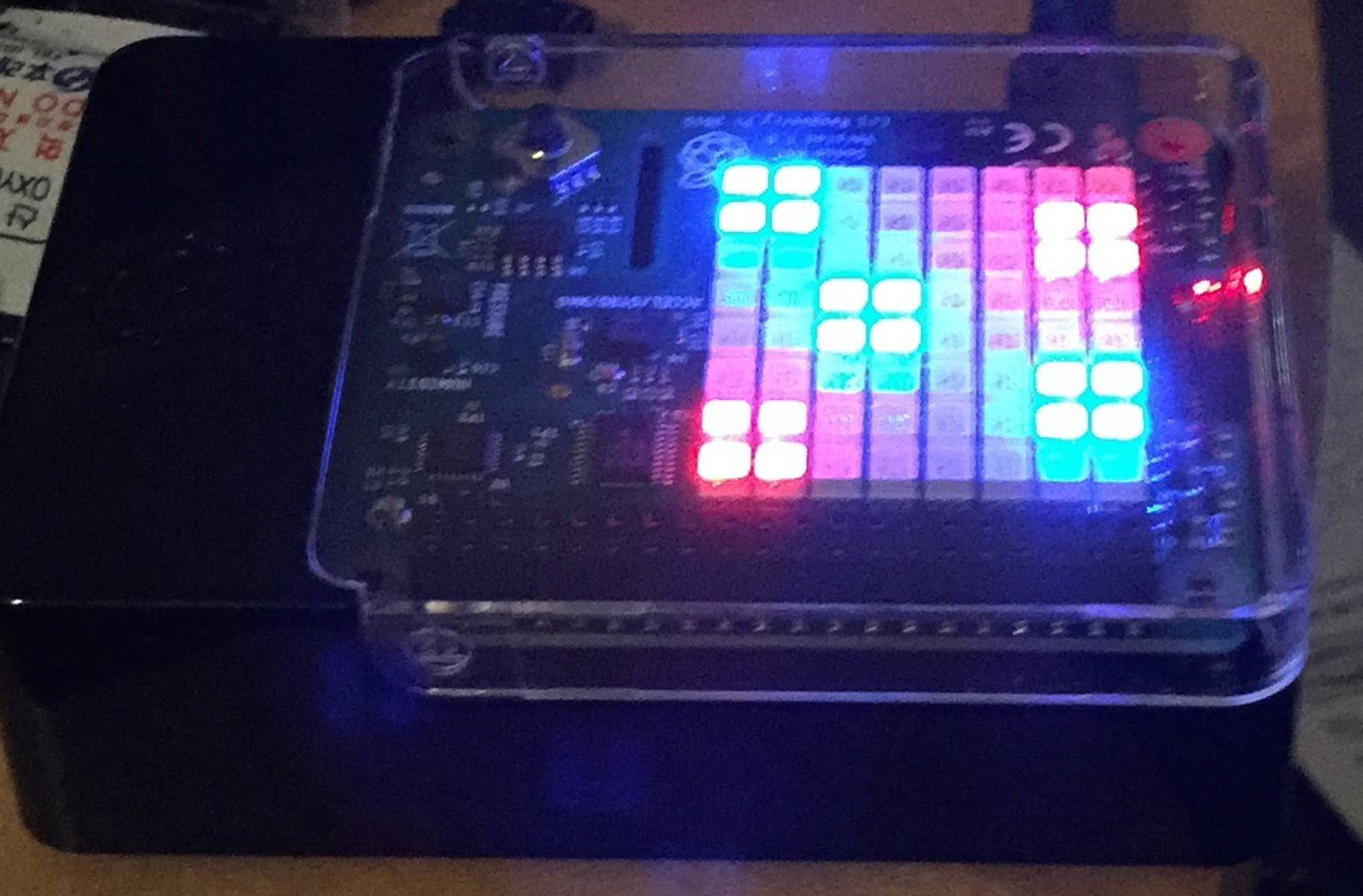
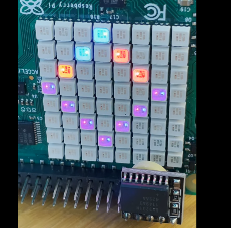
Comparing the same circuit on the simulator and on real hardware is the thing worth doing: the ideal result is crisp, and the real device shows you noise.
No LEDs? It also renders to an SVG you can open in a browser.
Credits and documentation
Written and maintained by Kevin Roche. The upstream project documents the display modes, backends and options in full — start there rather than here:
- KPRoche/quantum-raspberry-tie — the project and its documentation
- IBM Quantum Platform — for a free account and API key, if you want the
realvariant - Bill of Materials · Hardware Assembly Guide — for the LED panel
See the Demo List for everything else on the image.