Hardware Assembly Procedure
This section provides a step-by-step photographic guide on how to assemble the RasQberry Two Platform. The guide is divided into different sections based on the separate components of the 3D model, as well as a section detailing setup instructions for the Raspberry Pi. The three main components of the RasQberry Two platform are: The Wall, The Cryostat and The Floor.
Contributors
The following people have contributed to the development of the documentation:
Luka Dojcinovic, Andy Stanford-Clark, Eric H Jenney, Jan-Rainer Lahmann, Sascha Schefenacker
You can contact any of us with questions, concerns or suggestions for changes to the hardware specs and the assembly guide
Where to find the 3D files
This assembly guide assumes that you have already printed out the 3D files for the Wall, Floor, Cryostat and the RTEs. If you haven't already downloaded and printed the STL files, they can be found here.
Setting up the Raspberry Pi
In this section, we will be going through the initial setup process of the Raspberry Pi.
Our first step is to install the RasQberry Two Operating System (OS). Instructions for installing the operating system can be found here.
After you have finished flashing the OS image to the micro-SD card, you can insert it into the slot underneath the Pi as such:
Figure 1: Mounting location for the Micro SD card.
Once the OS has been installed, plug in the USB-C Power Supply into the Pi, connect a micro HDMI cable from the Pi to your monitor and plug in a USB keyboard into any of the USB ports on the back. If the OS installation was successful, you should be met with a login screen on your monitor. The standard username is rasqberry and the password is listed in the installation instructions above. Login with these credentials and you should see a desktop interface.
Next, we will enable SPI for the LED array to work. To do so, open a terminal window by pressing the CTRL + ALT + T keys at the same time. When the window appears, run the following command:
sudo raspi-config
You will be met with this screen:
In the menu that shows up, navigate to 3. Interface Options using the arrow keys and press enter.
Then, navigate to I4 SPI the same way and press enter again.
The dialog will ask you to enable the SPI interface. Hover over the option that says Yes and press enter.
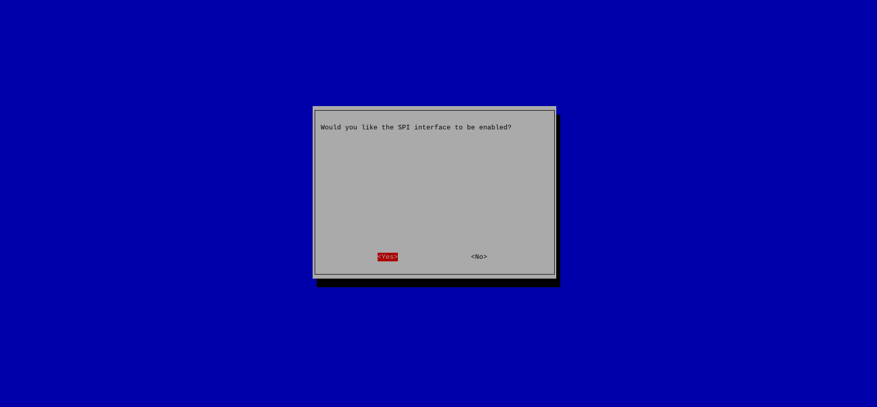 Now you’re all set to use SPI!
Mounting the fan
Before we can wire up the Pi and integrate it into the Wall, it is recommended to mount the Pi 5 Active Cooler onto the board.
Figure 2: The Raspberry Pi 5 and the Active Cooler.
The mounting process for the active cooler is quite straightforward. First, ensure that the protective film covering the bottom of the heat sink is removed:
Figure 3: Removing the film from the active cooler.
Then, line up the cooler so that it is over the two mounting holes. The correct orientation for the cooler is to place the end with the fan and the colorful cables close to the IO ports (USB, Ethernet etc.). Once you have lined it up correctly, place it down and gently press on the two spring buttons on opposite ends of the cooler. You will hear a click sound when the connector has successfully fastened. Flip the board over to verify that the plastic anchor is all the way through the board:
Figure 4: Correct mounting orientation for the active cooler.
Figure 5: View of the plastic anchor correctly secured through the board.
Finally, plug the colorful cable into the connector close to the top left spring button you just pushed. There may be a cover on the fan port when you first receive the Pi 5. If so, use some tweezers to gently pull the cover off. Once completed, simply plug the fan cable into that connector:
Figure 6: Fan cable plugged into the fan port.
Now you’ve successfully mounted an active cooler to your Raspberry Pi!
Figure 7: Raspberry Pi 5 with Active Cooler mounted.
Assembly of the Wall
The Wall is the part of the model that represents the server wall behind the real life IBM Quantum System Two. Our rendition of the wall houses all of the vital electronic components of the model and also serves as a housing for the LED display. This part of the assembly guide is likely the most intensive, but fear not; the process is relatively straightforward and when you’re finished you’ll have an amazing looking enclosure for your Raspberry Pi that also functions as a display for all the quantum demos!
Before we begin this guide, it is important that we cover the three main parts of the Wall. These are: The Wall Base, the Wall Back and the Wall Lid. These parts will be referenced throughout the remainder of this tutorial.
Figure 1: The three main parts of the wall.
The following 3D Files are used in this section:
-
R2_Wall-Back
-
R2_Wall-Base
-
R2_Wall-Lid (1)
Gluing all the pieces together
Depending on whether you printed the components for the wall yourself, and the size of your 3D printer, you might have needed to print the various parts of the Wall in two parts or even more. If you printed all of the components in one part, you can skip this step and move on to the section titled Wiring up the LED Arrays. For this guide, each major component of The Wall was split in two for easier printing. Once they finished printing, they were cleaned up of any remaining supports and stringing material.
Figure 2: Each sub-assembly of the Wall printed.
After cleaning the models, it’s now time to put them together! To ensure that the parts are securely attached, it is recommended to use CA Super Glue to glue the halves together. Super glue can be easily found in most stores, and is popularly sold under brands such as Gorilla Glue, Loctite, Adhear etc. For this guide, we will be using Gorilla Glue:
Figure 3: Gorilla super glue used to glue the halves together.
! Warning: Super Glue can very easily stick to skin and cause painful injuries. Please use caution when using super glue and never touch the glue while it is drying. Only use a small amount of glue, a little drop goes a long way.
Before gluing the halves together, it is recommended to lightly sand down the upper and lower “lip” of each half. This sanding process will create a smoother surface while also enabling the super glue to form a stronger bond between the two parts. Once sanded down, apply a small amount of super glue to both the upper and lower lips of the two halves and hold them firmly together.
Figure 4: Gluing one half of the Wall base.
Figure 5: Gluing one half of the Wall’s lid.
After the two halves have been glued and brought together, it is recommended to let them dry for at least 24 hours. To ensure that they remain connected over this 24 hour period, it is strongly encouraged to use clamps to hold the pieces together while they dry. The following is an example of that:
Figures 6 & 7: Using clamps to hold the pieces together while they dry.
Once 24 hours have elapsed, remove the clamps and verify that the halves are securely attached. If needed, more glue can be added at this point and the drying process repeated. When you are confident in the strength of the components, it’s time to move on to putting them together and adding the Raspberry Pi!
Wiring up the LED Arrays
In this section, we will be wiring the LED panels to the Raspberry Pi. Ensure that you have completed the section titled Setting up the Raspberry Pi before following these steps.
The LED array is composed of four identical WS2812IC LED panels. Each one looks like this:
Figure 8: One of the LED panels.
Each panel has two separate plugs; an input plug and an output plug to chain multiple panels together. The output plug has two latches on the side, while the input plug looks like this:
Figure 9: The input plug of the LED panel.
You will notice that the plugs have three wires; red, green and white. The purpose of these wires is as follows:
Red: This wire is the power lead. This is usually hooked up to 5V and provides all the power needed to turn the LEDs on.
Green: This wire is the SPI interface lead. This will be used to tell our panel which LEDs to turn on and off, depending on which program we run from the Pi.
White: This wire is the ground lead. This is needed to complete the circuit.
To connect the LED array to the Pi, we will need to use jumper wires to connect the Pi’s GPIO to the LED panel’s input plug. GPIO stands for General Purpose Input/Output; it provides a bunch of useful pins that can be used to connect a variety of add-ons and components to the Pi. For this step, we will need three Male to Female Breadboard Jumper wires:
Figure 10: Three color-coded M-F Breadboard Jumper wires.
Now, we need to connect these wires to the Pi’s GPIO on the female end and to the LED panel’s input plug on the male end. I have provided a pinout of the Pi 5’s GPIO below. The three pins we need to connect are circled in their appropriate wire colors.
Figure 11: GPIO Pinout of the Pi 5, with the needed connections circled in the wire color.
Connect the Red wire to Pin 2 (5V). Connect the White wire to Pin 6 (GND). Connect the Green wire to Pin 19 (SPI MOSI GPIO 10). Once finished, your wiring should look like this:
Figure 12: Wiring the Raspberry Pi.
Now we need to connect the male ends to the LED panel. The male end has a bit of exposed wire, this can be carefully slotted into the input plug to achieve a connection:
Figure 13: Plugging the male end of the jumper cable into the LED panel plug.
After plugging in all three wires, it should look like this:
Figure 14: Plugging all three jumper cables into the LED plug.
Now we’re going to connect that LED panel with the other panels in a chain. Find the output plug of the panel you just wired up and connect it to the input plug of another LED panel. Follow this process for the other two panels until you have a chain of four panels all connected together. You want to make sure they all have the same orientation. Orient your fist panel so that the top left corner has an arrow pointing downwards in the second column, then make sure that the other three panels have the same orientation and the same arrow in the top left corner.
Figure 15: Wiring all four LED panels together.
After ensuring that all four panels are in line, take the two panels on the right side and bring them down below the other two panels, this will essentially bring the two panels into an upside down orientation. Doing so will give you the arrangement of LEDs as they will be on the wall. Ensure that the bottom two LED panels have arrows in the top left corner pointing downwards in the first column.
Figure 16: Flipping the last two LED panels underneath.
! Warning: The LEDs can be very bright! It is recommended to wear eye protection when working with the LED panels.
Now it’s time to test the LEDs! Run the Python script in your terminal:
python3 neopixel_spi_IBMtestFunc.py.
If everything is wired up correctly, you should see the IBM logo appear on the LED array in the correct orientation. Verify that your result looks similar to this:
Figure 17: Testing the proper orientation of the LED panels before slotting them into the wall.
Finally, take the bottom two LED panels and slot them into the space in the wall between the thin pillars and the wider pillars.
Figure 18: Placing the bottom row of LED panels.
While making sure to preserve the LED orientation, slot the other two panels on top. You can rest the top row of the LEDs onto the black board of the bottom LEDs.
You can run python3 neopixel_spi_IBMtestFunc.py again to help you line up the columns together. Once you’re all done, it should look like this:
Figure 19: Both rows of LED panels lined up.
Figure 20: Resting the top row on top of the bottom row.
Figure 21: Testing out panel alignment using the IBM test function.
Congratulations! You have successfully wired up the LED panels with the Raspberry Pi!
Cutting the welding shield
The Wall uses the plastic sheet from a welding shield as a stand-in for the dark glass panels on the real world server wall. This sheet serves to obscure any LEDs that are off, as well as to dim the brightness of any LEDs that are on.
For this section, we will be using a pair of scissors and the welding shield itself, which looks like this:
Figure 22: The welding shield.
! Warning: Scissors and scalpels are sharp and can cause injuries if you are not careful. Please use caution when cutting the welding shield during this section.
On the welding shield, you will want to mark out a rectangle in the center that is 240mm wide by 83mm tall. The rectangle dimensions can be marked by using a bright colored tape or by using a scalpel and straightedge ruler to etch a shallow line that can be followed while cutting. It is recommended to add a few more millimeters to the width and the height while measuring, incase adjustments need to be made later on. Begin your measurements after the oval cutouts found on the bottom of the welding shield, so that your rectangle will not contain any holes.
Figure 23: Using tape, a straightedge ruler and a scalpel to mark out the lines to be cut.
Once you have marked out the dimenensions of the rectangle, use a pair of scissors to cut along the lines you have marked. The welding shield should be fairly easy to cut, use a little bit of force but go slow to ensure you are following the lines. Once you have cut out the rectangle, it should look like this:
Figure 24: The welding shield cut into a rectangle 240mm x 83mm.
Now it's time to slot the shield panel into the wall. The shield panel slides into the same gap you placed the LEDs panels into. We have found it is easiest to first remove all of the LED panels and then attempt to slide the shield panel into that gap. If the panel has difficulty sliding in, then it is probably too wide and needs to be trimmed a little on the side. The panel should slide relatively easily into the gap, if you encounter any resistance then you should trim the panel a little more. If you observe that the panel is causing the bottom of the wall to warp a little, then that also means that the panel is too wide and needs to be trimmed a little on the side. After you have made any necessary alterations and have ensured that the panel slides in with no resistance, you can return the LED panels back to the gap as well, making sure to preserve the orientation that was described in the Wiring up the LEDs section. When it's all finished, it should look like this:
Figure 25: The welding shield placed in front of the LEDs.
Try placing the Wall Lid on top of the Wall Base to ensure that the panel fits properly. If you notice that the Lid is not seating properly, then you might need to trim a little bit of the top of the panel to get it to sit properly. Your end result should look like this:
Figure 26: Placing the Lid on top of the Wall and ensuring it fits properly.
Now you have successfully placed the welding shield onto the Wall!
Place the Hex Bolts or 'screws' (R2_Screw) into the corresponding hexagonal holes at the bottom of the wall. It is helpful to do this last so that the wall can stand on its own in the mean time. These should fit snuggly. If not, a dab of glue will hold them in place until they are used to connect the wall to the floor.
Attach the Pi to the Wall
Now that the Pi has been wired up and the LED Array has been tested, it's time to secure the Pi to the back of the Wall.
Before moving on, attach the right-angle USC-C adapter to the USB-C port on the Pi. This will enable you to plug in the power cable while the Pi is inside the Wall. If you have a right angle adapter or cable for the Micro HDMI port as well, attach it to one of the Pi's display outputs. The display connection is optional, depending on whether you prefer to connect over VNC or use a wired display connection.
Locate the four screw posts on the Wall Back, they should look like this:
Figure 27: The four screw posts on the Wall Back.
Position the Pi over the four screw posts, lining up the the holes on the Pi's circuit board with the holes in the posts. Ensure that the orientation of the Pi is correct, with the GPIO wires on the top side of the plate, opposite the circular cutouts on the bottom.
Insert the four Tapping Screws from the BOM into each of the corner holes of the Pi. The screw posts do not have any threading when printed, so you must make your own by carefully turning the screw using a square bit screwdriver. As you turn it, apply light preassure until you feel that the screw has bitten into the plastic. If you are using machine screws with a flat end, you might want to try using a pointed screw first to make the thread, and then switch back to the machine screws to secure the Pi.
Ensure that you are not overtightening the screws. Use the screwdriver until the screw sits flush with the board, or you determine that the screw has gone in enough to provide a secure fit. The Pi is not very heavy, so it is better to err on the side of caution and only tighten to the point that you are satisfied with the connection.
If you find that the screws are a little too long, you can add small plastic washers to add more space. The washers might need to be trimmed a little to fit alongside certain parts of the Pi's circuit board. You can see in the image above an example of plastic washers being used, with some trimmed a little to fit.
Once all the screws have been tightened, the Wall Back should look like this:
Figure 29: The Pi attached to the Wall Back.
With the Pi fastened to the Wall, it's time to move onto the final step; putting it all together!
Assembling the Wall
With all of the Wall components secured and tested, we can now fully assemble the Wall.
The Wall Back attaches to the Wall Base using three hooks on each side of the Back plate. These hooks attach to three corresponding cutouts on each side of the Wall Base. The cutouts look like this:
Figure 30: Cutouts on the Wall Back.
To attach the Back and Base plates together, slightly angle the Back plate so that the three hooks come in above each connection point on the Base plate. Push the two parts together until the Back sits flush with the Base. As you push the two parts together, keep an eye on all of the wires from the Pi and LED panels. You want to gently move them into the space inside the Wall. Be careful not to bend any of the wires at a sharp angle so as to not damage them. Pay close attention to the wire connections with the GPIO on the Pi. There should be enough room for the wires to slightly curve away from the GPIO, leaving the female connectors securly attached to the GPIO pins.
Figure 31: Inserting the Back plate into the Base plate at a slight angle.
Then, gently push down on the Back plate until the gap between the Back plate and the floor of the Base is closed. Once finished, the Wall should look like this:
Figure 32: View of the Wall from behind, with the Back plate and Base plate attached together.
Finally, place the Wall Lid piece on top of the rest of the Wall. There are two small holes on either corner of the Wall next to the where the LED panels are. Line up the two connectors from the Wall Lid with those two holes for a secure fit. As you are lowering the Lid piece, take care to gently arrange all of the wires inside of the Wall. When the Lid is securly attached, your Wall will look like this:
Figure 33: View of the Wall fully assembled.
Congratulations! You have successfully wired the Raspberry Pi to the LEDs and assembled the Wall together!
Assembly of the Floor
The floor is the simplest component of the RasQberry Two model, it serves as a platform onto which the Wall and the Cryostat can be secured to. This section will walk you through how to connect the floor tiles together.
The following 3D Files are used in this section:
-
R_2Floor-all.stl
OR
-
R2_Floor-Tile1.stl
-
R2_Floor-Tile2.stl
-
R2_Floor-Tile3.stl
-
R2_Floor-Tile4.stl
-
R2_Floor-Tile5.stl
-
R2_Floor-Tile6s.stl
NOTE: If you have printed all of the tiles as one piece (R2_Floor-all.stl), you can skip the remainder of this section.
The floor comes in 6 different pieces, each piece is marked with a number that can be found on the reverse side. The pieces need to be arranged in the following configuration:
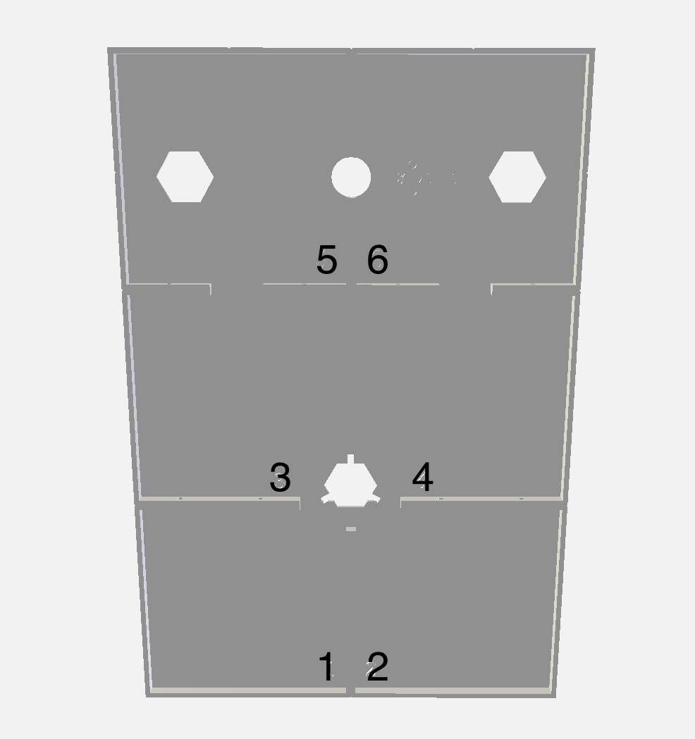 Figure 1: The correct order of the floor tiles.
Notice that tiles 5 and 6 at the top of the image contain the hexagonal cutouts for the Wall to be attached.
Each floor tile has two holes on each side where it connects to another floor tile. To connect the floor tiles together, line up two floor panels together so that the holes are in alignment. Insert an M3 Bolt (or #4 bolt in the US) through the hole and thread the nut onto the bolt until tightened. Reapeat the process to connect all of the panels together, making sure to preserve the correct order of panels as shown in the above image. We have found that holding the nut with a pair of pliers and using an allen key to tighten the bolt helps make the process easier, given the small space available beneath the floor tiles.
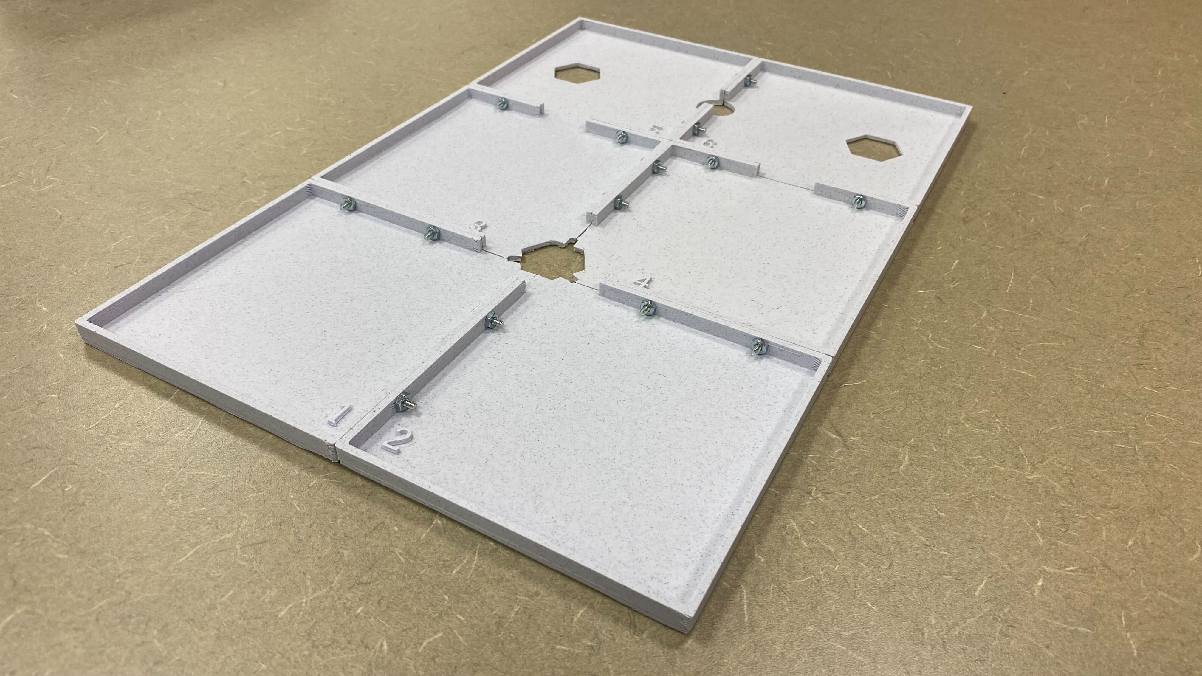 Figure 3: All the bolts and nuts tightened under the floor.
Once all the bolts have been tightened, place the floor on a flat surface for a while to let it flatten out. The finished result should look like this:
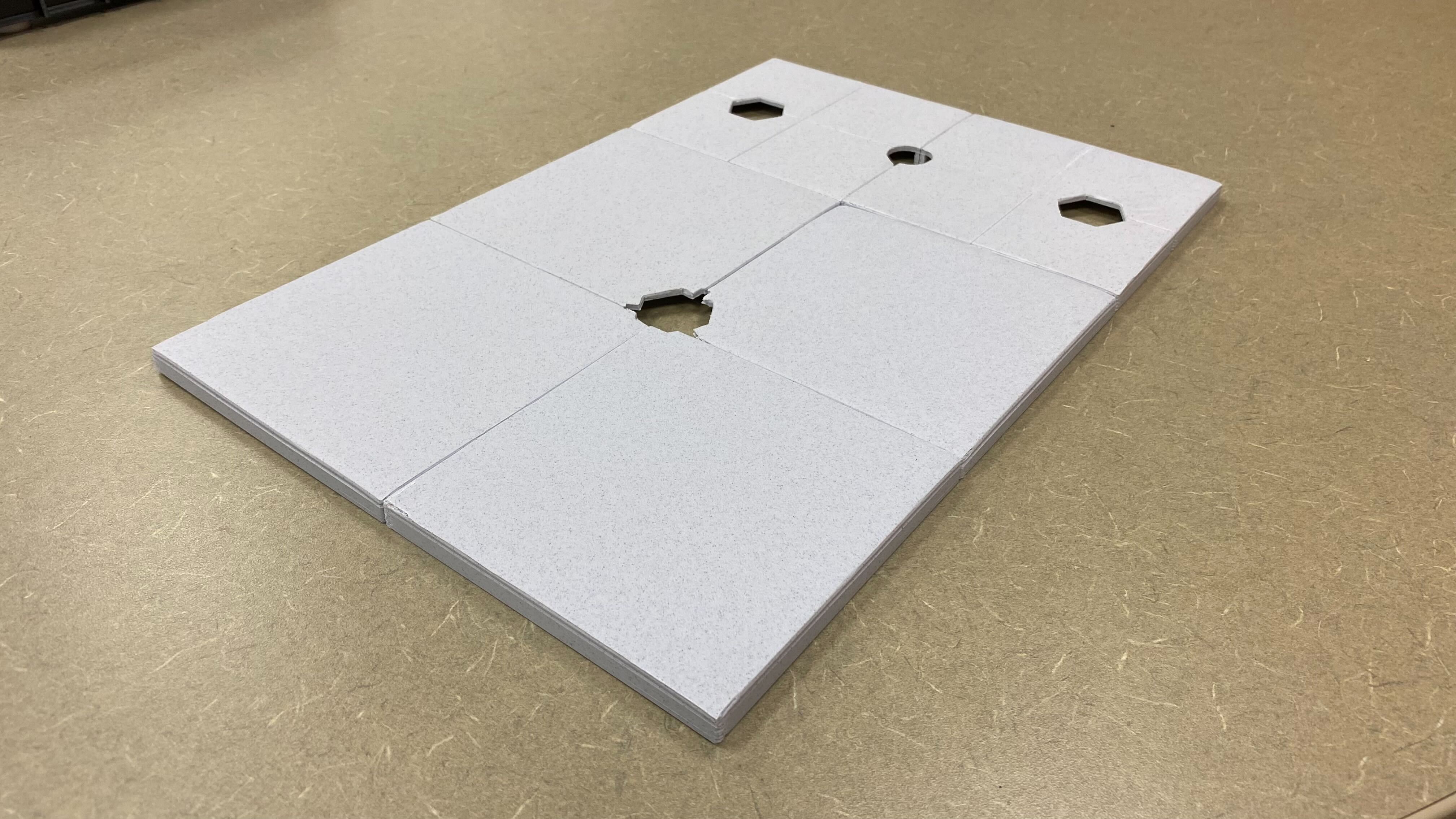 Figure 4: Top view of all the floor tiles assembled.
You have now successfully assembled the floor!
Attach the Wall to the Floor
Place the wall with the two protruding hex bolts into the hexagonal holes at the back of the floor.
Figure 5: Holes for the wall in the floor.
Fit the hex nuts to the bolts from the underside of the floor and tighten reasonably firmly, but only “finger tight”. They’re quite strong, but don’t over-tighten them.
Figure 6: The bolts of the wall, as seen from the underside of the floor.
Figure 7: The hex nuts tightened to the bolts of the wall.
Assembly of the Cryostat
The Cryostat comes with 2 RTE servers attached for each of the Chandeliers which would hold a processor. The core of the cryostat (R2_NarrowYCryoConjoined) is connected to the floor with a hex bolt as used in the Wall which has special 'arms' attached to conceal wires should you want to put anything electronic in any of the servers. The hex bolt, affectionately named the octopus (R2_OctopusAlignment) is made with the hex part slightly raised beyond the floor of the cryostat to ensure that the Cryostat is correctly aligned, and cannot move when twisted. You should first push the hex bolt all the way through the larger cryostat piece, then through the floor.
Figure 1: The octopus placed in the cryostat, as seen from above.
Figure 2: The protruding hex bolt of the octopus.
Fit the hex nut (from the Wall directory) through the underside of the floor and tighten reasonably firmly, but only “finger tight”. Again, don’t over-tighten them.
Figure 3: The hex nut tightened to the ocotpus.
The main Lid (R2_CryoLid-Simple) and Chandeliers (R2_ChandelierSingle) should be glued together. Print 3 Chandeliers, hex base down, and glue them to your “Cap”. You can print whatever color you want but we recommend the Silk Gold. They have a hollow core in case you want to do anything creative with LEDs or other wiring.
Figure 4: The three chandeliers and the cap laid out.
Figure 5: The chandeliers glued to the cap.
Each of the 9 RTE Servers (6 attached, and 3 stand-alone) requires a 'lid'. They are all the same file(R2_NarrowServerSingleLid). They just sit in place, in case you want to fit something inside the servers, but can be glued if desired.
Figure 6: Two examples of the RTE Servers.
The Door (R2_NewDoor) should be printed upright, so that the layer lines align, but may require a brim for stable printing. It and the server's door frame each require very small magnets for it to close securely... see the notes below on best practices for installing those.
NOTE: In the picture below, notice that the bottom magnet has been glued in while the top magnet has not been glued in yet.
The outside of the main Cryostat and RTE Server model and the inside of the 3 stand alone single RTE Servers (R2_NarrowServerSingle) connect with Magnets, alowing one to demonstrate the configurability of the system. Fit 2 large (15x2mm) magnets into the indents or pockets on the outer edge of each of the 3 RTE “arms”. Make sure they are all the same way round, so the RTEs will attach. Do the same with the individual RTE Servers.
Figure 8: The two large magnets glued inside the RTE server.
Figure 10: The cryostat cap, with chandeliers, inserted into the cryostat.
Figure 11: The fully assembled cryostat model.
Note: Tips for fitting magnets
Magnets have a life of their own, and can be very frustrating. Here are some tips the team has used to get them to go (and stay) where you want them.
Big magnets (15x2mm) sit in indents in the walls of the conjoined double RTEs and the separate single RTEs.
The magnets usually come in a stack, all pointing the same way. It’s important to install the magnets the same way round (all the same in the conjoined RTEs of the Cryostat, and all the same in the single RTEs, such that the RTEs attach to the Cryostat).
A good tip is to put a dot with a permanent marker (“Sharpie”) on the back of a magnet before you remove it from the stack. That way, the side with the dot on it is always the same polarity.
Use a dab of rubber solution glue (“Copydex” in the UK), applied with something like the blunt end of a pencil in the indent.
It’s easiest to fit the “lower” magnet first, then the “upper” one.
Use a spare magnet on the outside of the piece, and use that to steer the magnet on the inside into the patch of glue in the indent. Leave the magnet on the outside until the glue is dry (e.g. half an hour).
Small magnets (3x2mm) are very frustrating.
They are used to hold the door onto the Cryostat, and the lid onto the Wall.
The magnets usually come in a stack, all pointing the same way. It’s important to install the magnets the same way round (all the same in the Cryostat door frame, all the same in the wall base, all the same in the door, and all the same in the Wall lid, such that the door attaches to the Cryostat and the Wall lid attaches to the Wall base).
A good tip is to put a dot with a permanent marker (“Sharpie”) on the back of a magnet before you remove it from the stack. That way, the side with the dot on it is always the same polarity.
It is helpful to make a “handle” using 3 magnets wrapped up in Scotch tape / Sellotape (to keep them together and to make it easy to wipe any glue off). Use this to pick up a magnet and push it into one of the indents. Note that you will have to reverse the handle and use the other end to insert half of the magnets, so they have the correct polarities to attach to their other halves.
Use a dab of rubber solution glue (“Copydex” in the UK), applied with something like a cocktail stick in the indent, and then push the magnet in using the handle.
Attach another magnet to the back of the plastic wall to keep the magnet in place while the glue dries (about half an hour). Leave plenty of time for the glue to dry before assembling magnetic joints, so the magnets don’t pull out.
Roll any excess glue off with your finger when it’s dried.
Assembly Complete
If you've reached this point in the assembly guide, congratulations! You have successfully assembled the RasQberry Two model! 🎉
Be sure to check out the Quantum Computing Demos section of the website to learn about some quantum demos you can run on your completed model.
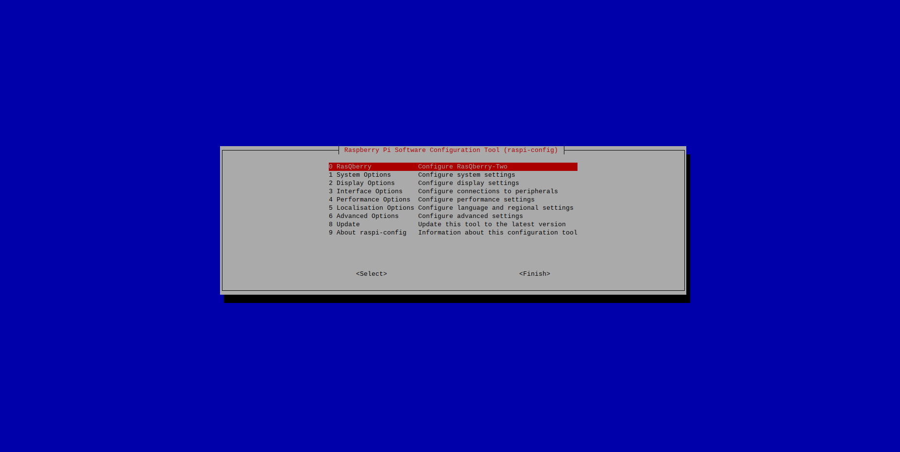
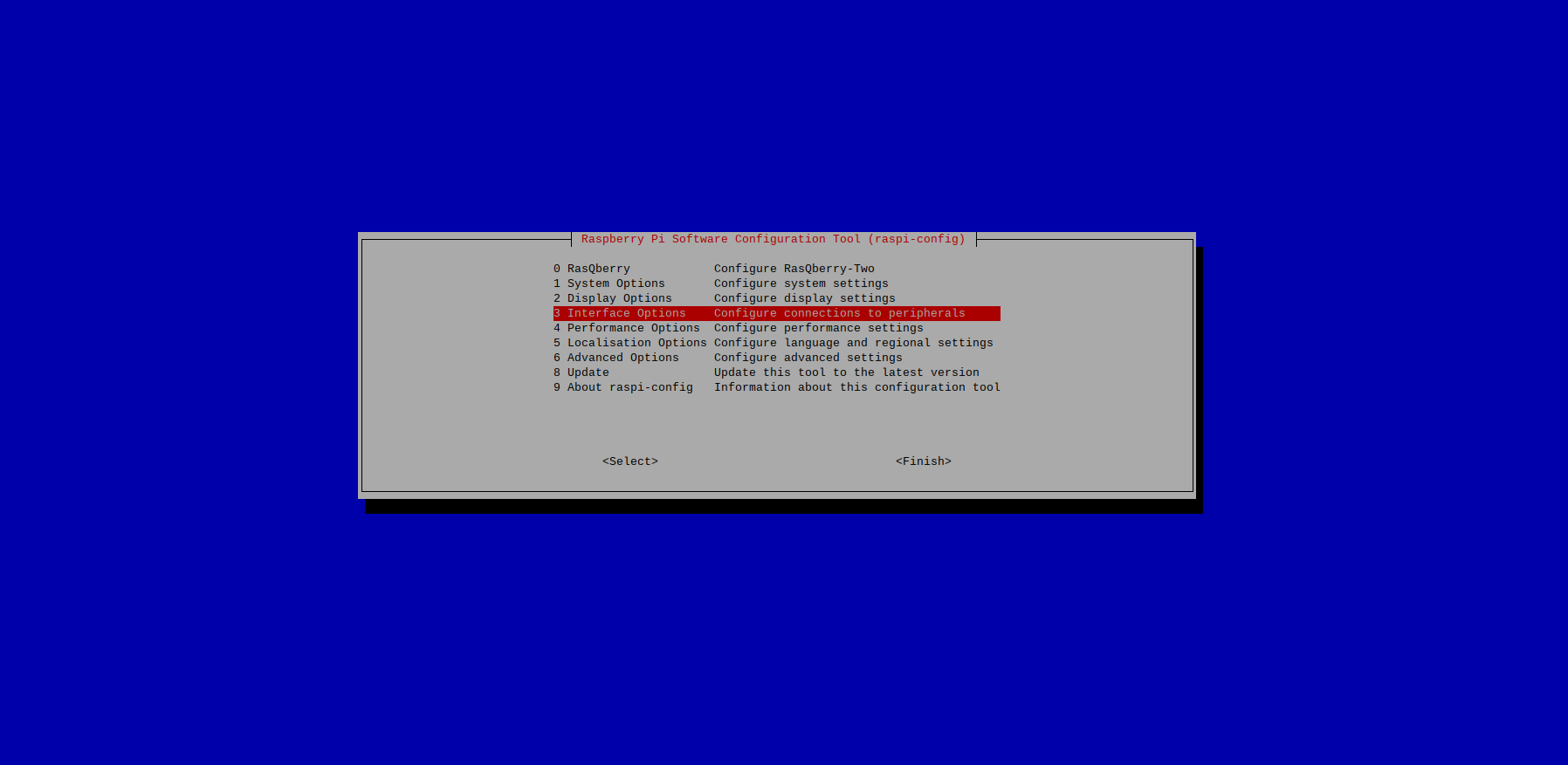
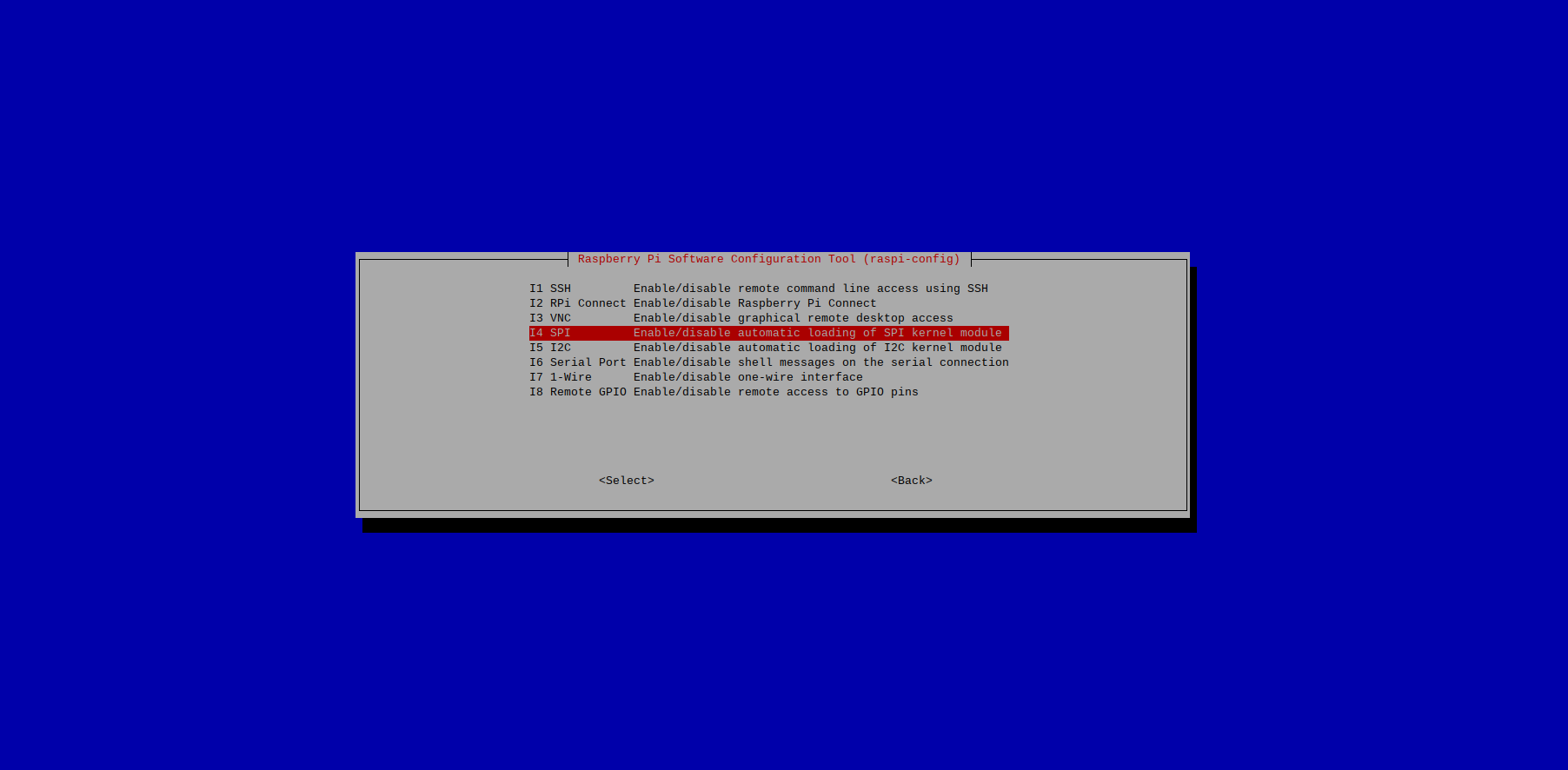
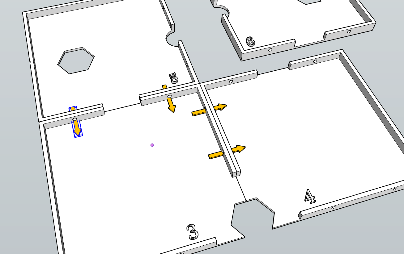 Figure 2: How to attach floor tiles together. The yellow arrows show where the bolts should be inserted and tightened.